- Product Name
- Product Keyword
- Product Model
- Product Summary
- Product Description
- Multi Field Search
Views: 203 Author: Site Editor Publish Time: 2018-03-05 Origin: Site

The basic operation of any stepper motor relies on the use of inductive coils which push or pulls the rotor through its rotation when they are energized. A pair of wire leads coming from a stepper motor will correspond to at least one of these windings and possibly more depending on the motor type. In each of the following cases a chassis ground lead is also pictured to ensure the motor is correctly grounded.
While many motors take advantage of 6- and 8-wire configurations, the majority of bipolar (one winding per phase) stepper motors provide four wires to connect to the motor windings. A basic 4-wire stepper motor is shown in Figure 1. Connecting this motor type is very straightforward and simply requires connecting the A and A' leads to the corresponding phase outputs on your motor drive.

Figure 1: 4-Wire Stepper Motor
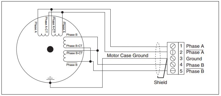
A 6-wire stepper motor is similar to a 4-wire configuration with the added feature of a common tap placed between either end of each phase as shown in Figure 2. Stepper motors with these center taps are often referred to as unipolar motors. This wiring configuration is best suited for applications requiring high torque at relatively low speeds. Most National Instruments stepper motor interfaces do not support 6-Wire stepper motors, although some motors do not require the center taps to be used and can be connected normally as a 4-wire motor.

Figure 2: 6-Wire Stepper Motor (Left) 8-Wire Stepper Motor in Parallel (Right)
Some motors are also offered in 8-Wire configurations allowing for multiple wiring configurations depending on whether the motor's speed or torque is more important. An 8-wire stepper motor can be connected with the windings in either series or parallel. Figure 3 shows an 8-Wire stepper motor with both windings of each phase connected in series. This configuration is very similar to the 6-wire configuration and similarly offers the most torque per amp at the expense of high speed performance.

Figure 3: 8-Wire Stepper Motor (Series Configuration)
It is also possible to connect an 8-wire stepper motor with the windings of each phase connected in parallel as shown in Figure 4. This configuration will enable better high speed operation while requiring more current to produce the rated torque. This connection type is sometimes known as parallel bipolar wiring.

Figure 4: 8-Wire Stepper Motor (Parallel Configuration)
Although every stepper motor operates in the same basic way, it is important to understand the difference between each wiring type and when each should be used.
The basic operation of any stepper motor relies on the use of inductive coils which push or pulls the rotor through its rotation when they are energized. A pair of wire leads coming from a stepper motor will correspond to at least one of these windings and possibly more depending on the motor type. In each of the following cases a chassis ground lead is also pictured to ensure the motor is correctly grounded.
While many motors take advantage of 6- and 8-wire configurations, the majority of bipolar (one winding per phase) stepper motors provide four wires to connect to the motor windings. A basic 4-wire stepper motor is shown in Figure 1. Connecting this motor type is very straightforward and simply requires connecting the A and A' leads to the corresponding phase outputs on your motor drive.

Figure 1: 4-Wire Stepper Motor
A 6-wire stepper motor is similar to a 4-wire configuration with the added feature of a common tap placed between either end of each phase as shown in Figure 2. Stepper motors with these center taps are often referred to as unipolar motors. This wiring configuration is best suited for applications requiring high torque at relatively low speeds. Most National Instruments stepper motor interfaces do not support 6-Wire stepper motors, although some motors do not require the center taps to be used and can be connected normally as a 4-wire motor.

Figure 2: 6-Wire Stepper Motor (Left) 8-Wire Stepper Motor in Parallel (Right)
Some motors are also offered in 8-Wire configurations allowing for multiple wiring configurations depending on whether the motor's speed or torque is more important. An 8-wire stepper motor can be connected with the windings in either series or parallel. Figure 3 shows an 8-Wire stepper motor with both windings of each phase connected in series. This configuration is very similar to the 6-wire configuration and similarly offers the most torque per amp at the expense of high speed performance.

Figure 3: 8-Wire Stepper Motor (Series Configuration)
It is also possible to connect an 8-wire stepper motor with the windings of each phase connected in parallel as shown in Figure 4. This configuration will enable better high speed operation while requiring more current to produce the rated torque. This connection type is sometimes known as parallel bipolar wiring.

Figure 4: 8-Wire Stepper Motor (Parallel Configuration)
Although every stepper motor operates in the same basic way, it is important to understand the difference between each wiring type and when each should be used.