
- Product Name
- Product Keyword
- Product Model
- Product Summary
- Product Description
- Multi Field Search
Views: 36 Author: xia Publish Time: 2020-06-02 Origin: Site
The Stepper motor is a typical mechatronic component. Compared with an ordinary DC motor, its internal structure and control principle is more complex. It can be divided into a hybrid(HB type), permanent magnet(PM type), and reactive(VR type). the structure of the HB type has some characteristics of PM type and VR type, and the control principle is the most complex, which involves deep electromagnetic theory. It is relatively difficult for those with weak electromagnetic knowledge to master. In addition, different control methods will be used on different occasions, which results in beginners to master the use of stepper motor for a long time.
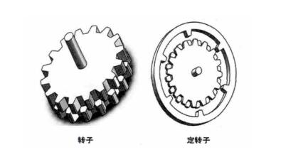
Stepper motor is electromagnetic equipment that transforms the electric signal pulse into corresponding angular(linear) displacement. The hybrid stepper motor has the characteristic of axis excitation and radial excitation. Its rotor and stator have many grooves, which forms teeth. The core of the rotor contains permanent magnet steel. From axial, the rotor can be divided into a, b section.
The teeth on the two sections of the iron core are staggered by half of the pitch, that is, the tooth top of a is opposite to the tooth slot of section b. and the corresponding teeth on the stator also appear in pairs. If the motor is three-phase, it has three-pairs, which is wound by winding, and the tooth width is usually the same as the rotor.
For hybrid stepper motor, when the rotor magnet is magnetized and a certain phase winding of stator is energized. Under the interaction of the rotor magnet and the stator magnetic force, the rotor has a certain stable equilibrium position. The stable equilibrium position is: when the polarity of stator and rotor are opposite, the magnetic conductivity is maximum. When the polarity of the magnetic pole is the same, the magnetic conductivity is the minimum. That is, when the polarity of stator teeth and rotor teeth is different, the teeth are opposite to the teeth, when the polarity of the magnetic pole is the same, the teeth are opposite to the grooves.
When winding the stator winding, the lead-wire at the end of section A is positive, that is, A+, B+, C+, and the lead-wire from the end of section a to the end of section B is negative. that is, A-, B-, C-. Energizing the windings from different directions(positive or negative) will cause the corresponding stator poles to produce different polarities.
It is assumed that the rotor magnetic steel section a is N pole, and section b is S pole. From one end the motor to see, as shown in pictures 2.1 and 2.2, when one tooth of the stator(magnetic pole A+) coincides with the axis of the rotor tooth 2, at this time, the A+ is powered on, the stator teeth are S pole. Because the rotor a, b segment are staggered by 1/2 pitch, so in the b segment, the corresponding stator pole faces the rotor slot. According to the principle of balance position, this is a balanced position. The angle between the two teeth of the stator is 60 °, the angle between the two teeth of the rotor is 45 °, 60/45=1+1/3. in terms of section a (viewed in the B- section), the rotor teeth 3 are staggered by 1/3 pitch(positive in the counterclockwise direction), for section b(viewed in the B- direction), as shown in 2.2, the rotor teeth 12 and the stator teeth(pole B-) is staggered by 1/3-1/2=-1/6.

When A+ is powered off and B- is powered on. According to the principle” when the stator and rotor is opposite polarity, the pole magnetic conductivity is maximum, when the stator and rotor are the same polarities, the pole magnetic conductivity is minimum.” the stepper motor should rotate 1/6 tooth pitch in counterclockwise, to make the teeth of the stator and rotor of section B match the teeth and the teeth of section a face the slot. Another balance position, as shown in picture 2.3 and 2.4. that is, rotate 1 / 6 × 450 = 7.5 °.
At this time, as shown in picture 2 and 4, the stator pole and rotor tooth 13 of section B (viewed from the direction of C +) are staggered by 1 / 3 pitch, while section a is shown in picture 2.3, the stator pole and rotor tooth 5 are staggered by - 1 / 6 pitch.
So, when the B- is powered off, energize the C +, and the rotor will turn 1 / 6 pitch in the counterclockwise. And so on: power sequence is A +, B -, C +, A -, B +, C -, rotor rotates 6 × 7.5 = 45 °, Rotate 8 times for 1 cycle. Thus, the rotation of the hybrid step motor is completed.