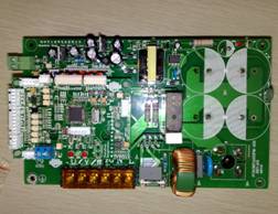
Brushless Motor Driver C-1500-220
Application
CNC Lathe, CNC milling machine, Drilling machine , spindle motor , controlled by Mach 3
Matched motor : D925, D1235 Model
Summarize
◆ AC220V power supply for
◆ Rated power 1500W
◆ rated speed to 6000RPM, speed range of 400-6000RPM, acceleration time 5S.
◆ PID closed-loop speed and current dual-loop regulator, speed-loop control accuracy of ± 1%
◆ has a limited flow, start-up failed, blocking switch, the module protection
◆ have the machine stop switch, protective masks, opening the door electronically controlled limit protection
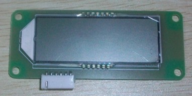
◆ LCD display with the actual speed machine tool spindle and the work of the drive, and speed showed an accuracy of ± 2%
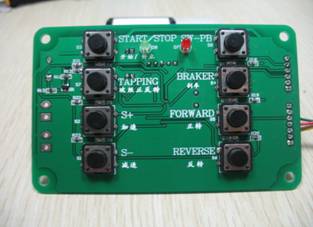
◆ regulating the use of key board drives the work of the state, operation is simple and convenient
◆ outside the user interface used to control the work of the drive, and easy to implement digital control of the working drive.